Posts Tagged ‘fiat’

I figured I could take a short break from demolishing my new home to regale you with a tale about a brace of plump pheasants.

My daily commute is your typical 20 mile moron jam.  Most of the road is 70mph dual carriageway but you are lucky to average 40.  So on my journey home I usually take the path less trodden, rural country roads where it is possible to average (ahem) the 60mph National speed limit.  About a year ago I was blasting along in my Grande Punto, singing along with the Red Hot Chilli Peppers when I large pheasant trotted out into the road ahead of me.  I braked to give it a sporting chance but I wasn’t about to end up in a ditch for it, so the outcome was inevitable.  Of course he couldn’t just go quietly, dispatched swiftly by the bumper, he had to try and haul his fat ass off the ground and ended up going straight through the radiator grill. Pheasant 1 – FIAT 1

Fast forward two weeks and I’m barrelling along the same road in the wife’s 500, blissing out The Black Keys when my peripheral vision locked on to a hostile projectile coming in from 10 O’clock at an altitude of about 8 feet.  It was plump pheasant’s kinsman with revenge in his heart!

At the time it was actually comical.  The pheasant was so fat it looked like a football.  It actually flew like a football that had been chipped over the hedge, descending in a lazy parabolic arc until it hit the round plastic bumper on the nearside front of the 500.  It bounced off the bumper, I could swear it even made a “boing” noise and flew back over the hedge with exactly the same trajectory.

The 500 bumper popped back to shape with nothing but some crazing of the paint to show for the ordeal.  Unfortunately the lights didn’t fair as well with both the headlight and driving light being broken off their mountings.  So that’s Pheasant 2 – FIAT 2

Fast forward a year and again I’m Rolling along that road with Limp Bizkit, when the water level warning sounds and the temperature gauge goes off the clock.  I limped, formula 1 “lift and coast” style to a near by garden centre for a splash of water before limping home.

WP_20150426_12_00_31_Pro     WP_20150426_12_54_49_Pro


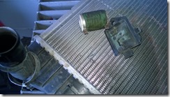
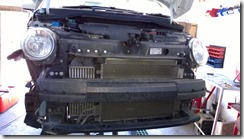
Upon investigation I found that right behind the impact point, on the inside of the radiator cowl was the cooling fan resistor, which had been broken from it’s mounting and become wedged between cowl and radiator cores.  It had bounced around in there until the spade like connectors had punctured the core.   Game, Set and Match Mr Pheasant.  Well played!


The final step in this merry dance was to attach the filler neck and tank supports in exactly the right places to fit the original mountings and have the filler neck pass precisely through the chassis outrigger I made in an earlier post. There is a fair bit of free space around the tank but it’s surprising how quickly a few millimetres here and there add up to components rubbing on things they shouldn’t touch.

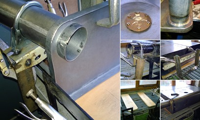
The easiest way to replicate the layout of the original tank is to use it as a template, so I raided the scrap bin for bits of Dexian and odds and ends to make a jig. By bolting, clamping and welding together a ramshackled collection of scrap I was able to fix critical points in mid air and after removing the old tank, use those points to locate the new.

The jig allowed me to position the filler neck and align the mountings on the end plate, holding them in place while I spot welded the mounting bracket and silicon bronze welded the the filler neck.  After adjusting for the movement caused by expansion and contraction I tacked the end plates into position in the skin with silicon bronze, then removed the tank from the jig to braze all the way around the joint.  Reposition and repeat for the other end.

With the tank closed up the only remaining construction task was to fit the breather pipe.  A piece of 15mm steel pipe which I bent to shape with my plumbing pipe bender, carefully positioned and brazed into the top of the tank.  I then closed the sender unit hole with a roughly made blanking plate ready to seal the inside of the tank with a commercial tank sealing kit.  Although there is obviously no rust inside my new tank it is important to protect the steel from the damaging effects of modern Bio-fuels.  The first stage of the sealing process is to use Metal Ready to passivate the inside surfaces and filling the tank with this also proved that there are no pinholes in my joints.  I bought a big enough kit to do the Spider tank too, so I’ll prepare that and seal them both at the same time…..But there is something else afoot right now!

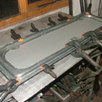
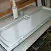
With the baffles completed the first stage of assembly was possible.  My plan was to form the shell around the baffles and tank ends leaving only part of the top open for access. Once everything was clamped in place I’d check the position of the sender unit then fold down the last section of skin and secure that too. Then I’d carefully remove one end and spot weld the skin to the baffle assembly, re-clamping the end when done before repeating the process from the other end of the tank.  I’d specifically designed the flanges of the baffles to be within reach of my spot welder arms.

View albumView albumView albumView albumView albumView albumView albumView albumView albumView albumView albumView album

The tank ends needed a bit more work before they could be fitted but this required the main body of the tank to be completed first.  That’s something I’ll cover in my next post.

A petrol tank, especially one that is flat and square like this needs baffles to prevent the fuel sloshing around inside.  You need to keep the fuel pick up pipe submerged or you’ll splutter to a halt every time you change direction and you don’t need the weight of a tank full of fuel with a mind of it’s own under you while you’re driving.  No, you  want the fuel to move to the pick-up pipe in an orderly fashion, thank you very much!

I made the transverse baffles using the same hammer-form I used for the ends.  Fortunately I didn’t need to form corners on these components as this is where the fuel will get past. The longitudinal baffles run about 1/4 of an inch from the skin, which will prevent surge but allow good flow to the pick up sump.

The whole assembly was dry fitted to check the position, then spot welded together to be fitted to the final assembly in one piece.

It’s all about the joints!  I wanted to make it in one to avoid having too many, so some careful planning was needed….

I’ve got pretty good spatial awareness but I have to confess to some surprise when I worked out how big a sheet of steel I would need to roll the outer skin of my Amigo tank in one piece.  There wasn’t a lot of spare from a 4 foot sheet.  I usually work alone but a sheet this size takes some handling, I’d have struggled if it weren’t for my lovely assistant Jules.

I planned the layout to ensure that the joint in the sheet would be on the uppermost surface, giving one less weld to potentially leak. The sender unit posed the greatest challenge, with it’s mounting ring in the top of the tank and a pick-up sump in the bottom.  These had to be positioned in the same location as the original tank to meet up with the connections and coincide exactly for the pick-up and fuel gauge to work correctly.  My old Dad always says “measure twice, cut once” but I must have measured about a dozen times before I committed!

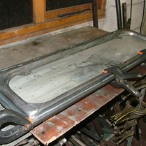
With everything marked out and double checked I had to create the two “blisters” in the skin.  This was what I made the Pixie’s Toilet Seat for in an earlier post.  I decided (wisely as it turns out) to run a test before attacking my pristine sheet of 20 Gauge Zintec and soon discovered that my air chisel would not generate enough stretch to form the blisters.  I needed to pre-stretch the area whilst still keeping my blisters accurately located so Thor and a beater bag were deployed.  I took great care not to influence the register marks that located the sheet in the hammer form.  After stretching, Jules and I smoothed the resultant walnuts in the wheeling machine.  Finally it was back to the hammer form and air hammer.

After forming the blisters I crudely rolled the skin over some steel tube, roughing out the bends to ensure they were located correctly.  Once I was happy that I wasn’t wasting my time to continue I punched out the aperture for the sender and checked the ring I’d made earlier fitted.  Looking good so far…

The tanks ends were the next components to take shape.  They are identical in construction, geometrically mirroring each other, although one was destined to have a hole for the filler neck added at a later stage.

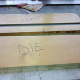
My hammer forms, made from tough plywood are identical.  I marked the most accurate half as the die but wasn’t sure if the plywood would withstand the rigours of making two pieces.  With two identical forms I had the option of switching to the second one if the first lost it’s crisp edges.  As it turns out I needn’t have worried as the die survived almost unscathed.  Just as well because I had further plans for it….

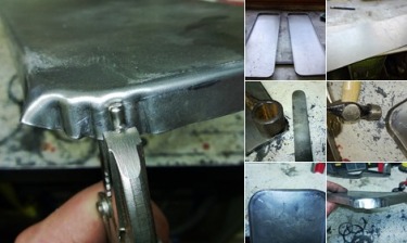
I learned an awful lot from these pieces.  I got nice crisp angles but couldn’t get anything like enough shrinkage on the corners hammering onto the plywood.  I tried heat but with only a blowtorch, was not successful.  I found a piece of Transit van leaf spring which was just the right radius for the corners and used a combination of tucks using my vise grip crimping tool and hammering onto the makeshift dolly to get it close. Then I switched to a technique that I’ve seen done by others, David Gardiner demonstrates it on his training DVD but I’d never been able to master it.  Practice makes perfect though and eventually it clicked!  The technique involves hammering obliquely on the edge of the turned flange to force the metal into itself.  The angle of the blows, weight and effort all require precision and this is something you have to learn with practice.  The first couple of corners I chased the spare metal back and forth but by the eighth corner I was a dab hand!

With my house literally like a building site I decided to start with some of the small but critical parts of the build, rather than tackle the larger components that would necessitate me trying to work in the garden.

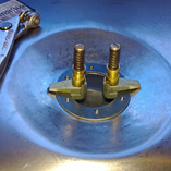
The sender unit mounting requires a reinforcing ring with attachments.  The original had captive studs but a 4mm thread stuck on top of a mud trap like the tank hasn’t got a snowballs chance in hell next time I need to remove it so I reversed the design and attached captive nuts to the tank and will use stainless socket head bolts to fit the sender.  There is a risk that fuel will seep through the threads but a drop of thread-lock should prevent this.  A spare piece of 1.6mm steel plate was duly sacrificed and using a combination of hole punch and plasma cutter the ring took shape.  To avoid distortion I TIG brazed the captive nuts in place.

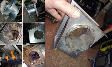
The next sundry item to form was the filler neck.  The original was an awkward size, at 50mm diameter it fell between the two sizes of exhaust pipe I happen to have in the oddments bin.  Nothing else for it but to roll my own.  Pythagoras helped me work out the dimensions of my sheet and I rolled it around some scrap tubing and zip-tied it into shape.  Following a buzz with the TIG I rolled a flange with my bead roller and Bob’s your live in lover.

The original tank is formed of two half-shells, resistance welded in a continuous bead around the perimeter of adjacent flanges.  There are a couple of simple baffles inside to prevent fuel surge along with a matching male and female indentation for the pick-up point and sender unit respectively.  I initially considered making a replica of this arrangement for my replacement but soon realised, as I visualised the construction process in my mind that this design would be difficult to realise with the tools I have available.  There were clearly design elements I must adopt but with something as critical as a petrol tank I couldn’t afford to take any chances, so I revised my design to allow me to form it without risk of compromise.  I also opted to increase the capacity of the tank by about a gallon by increasing it’s width. It’s not a very big tank and an extra 35 miles range, give or take is not to be sniffed at.

I opted to make the tank shell in 3 pieces; two end panels with a single skin wrapped around them rather like a barrel.  The baffles would be two panels of similar form to the ends joined by two transverse panels.  By assembling the baffles first the tanks skin would wrap around all of the vertical members and join at the top where the likelihood of leakage is lowest.  The end panels could be removed, granting access to secure the baffle system with spot welds (something the original “shell” design wouldn’t permit), then replaced and welded into place.

View albumView albumView albumView albumView album

Using a standard sender/pick up unit was essential, so the two indentations were a necessity.  To create these I opted to use a Hammer form.  I formed an elaborate device I call The Pixie’s Toilet Seat (you’ll see why) from some scrap timber and a T-hinge which was ultimately destined to hold up my new garden gate.  No wastage here!  The pixie’s toilet seat allowed me to hold two concentric circles in register to each other.  By clamping steel sheet in between I could hammer a circular indentation with clearly defined inner and outer diameters.  A test run proved that quite a lot of pre-stretching was required, which I achieved with hammer and dolly and English wheel. The end panels and baffles were also created using a simple hammer form consisting of two pieces of scrap plywood.

Next installment…I start bashing tin!

It’s that time of year again when I inevitably succumb to the heinous cocktail of germs that the new influx of students bring to my workplace.  I really cannot afford to lose this time, either at work or home but short of calling in Hans Blix I’m sure “Fresher’s Flu” will continue to be an occupational hazard until we can eradicate the common student…I mean cold!  So in between the fever/shivers/aching cycle I thought I’d take the opportunity to begin the saga of the Amigo petrol tank.

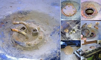
I’ve been concerned about the tank on the camper since we bought it.  There was always rusty water in the inline filter.  So having reached the point where I needed to weld the sill right next to the tank I figured it was the opportune moment to drop it down and refurbish it.  The Spider also has a steel tank which will need protecting from modern bio-fuels, so I bought a kit from Frost that was big enough for both tanks.

I dropped the tank down, drained and flushed it out with hot water.  Then I filled it with the Marine Clean industrial degreaser which did it’s job for a couple of hours and then was recovered and the residue rinsed out.  All was going well.

The next step was to fill the tank with rust remover.

The kit comes with Metal Ready but I had a large quantity of DEOX-C mixed up and decided to use this initially.  It’s very impressive stuff.  I half filled the tank and left it on the bench to stew.  The following day there was a steadily growing puddle around the bench and the bottom of the tank looked like a Tetley’s Tea Bag.  Closer inspection revealed a number of places that had been soldered up in the past.

Now the tank sealant in the kit is claimed to repair small holes like these but to be honest, I’m not keen to give it the benefit of the doubt when I’m likely to be sitting inside this van with a gas cooker blazing away.  It had to be a new tank!

I’ll describe the design process in the next instalment.

I’ve been so busy over the last few weeks I’ve not had a chance to blog.  My day job is frantic, I’ve had a jolly to Norway, which is nice…I’d move there tomorrow! And I’ve got the builders in to extend my house.  I’ve still found some time to get a bit done though.

I’ve done a bit of archaeology, digging out the remains of a door from what seems like centuries of filler build up!  There is little detail of the original panel so I had to take great care not to destroy the only evidence of what shape the door skin should be.  I think I’ve got a good pattern from it, we’ll soon see!

Progress has been steady over the last few weeks, I’ve had a lot of other stuff on my plate. I’ve refurbished a bicycle for my 5 year old Nephew, work has been chaotic and we’re in building work limbo, awaiting the commencement of work on an extension but I’ve been plodding on with Pandora.

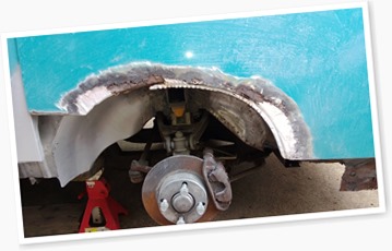
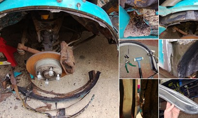
The front wheel arches were badly bodged with filler. It was difficult to discern exactly what shape they were supposed to be, so rather than attempt to make them I ordered some from Italy.  They were NOT cheap but it was a supplier that I’d used before so I was reasonably confident that they would actually show up!  Most of these old stock panels have been on the shelf so long that they’re scratched and beginning to show signs of dry rust.  So they went straight into a bin of caustic which fetches the paint of in no time, then into a bin of Bilt Hamber Deox-C. The stuff rocks!  The black passivated panel then coated with Zinc galv paint which provides pretty good Long term protection (but Weld-Thru my arse!).

Behind the arch and under the tub is an intermediate panel that forms a box section with the new arch panel…or at least there should be, there wasn’t much left.  So with the new Tank Roll bead roller dies I recently purchased I tried my hand at making a new one, similar if not exactly matching what I thought the original looked like.  It was pretty successful for a first attempt and easily good enough.  The rearmost section of this panel is a little more complex in shape and I made this separately using an FSP.  I clamped the new arch to the new sill I made earlier and fitted the intermediary arch panel to the assembly.  The tank rolls were quite frankly obscenely expensive for Made in China crap but they’ve worked well.

I’ve started to strip all the underseal and paint from the tub and there are some repairs needed there.  I went nuts with the plasma cutter and spot weld cutter to strip off the old arch and badly repaired sections of floor and chassis and things are looking hopeful for reassembly before the builder arrives!  I’d desperately like to see some progress, as forever cutting more rust off it gets pretty demoralising.  Here’s hoping.

I spent Sunday making something I will never, ever use.  The jacking points on these old FIAT’s are like nipples on a man, (apart from proving that our “Creator” hates joggers) they serve no useful purpose.  The original jacks were rather like the old “monkey up a pole” affair but they had a winding handle at the top to drive a screw thread.  What invariably happened when you used them was that on all but the most even ground, the vehicle weight would shift and the top of the jack would dig into the bodywork about a foot above the jacking point.

The jacking points are useful in that they are a clear indication to tyre monkeys as to where they should jack and I also favour originality.  So I had to create new ones.  I got an excuse to play with the Plasma cutter too and that’s always fun.

I cut some 2mm plate and went to work with my vice bending brake.  It was heavy going, I even bent the handle on my vice but I got there.  The first one needed a tweak or two because it’s not easy getting dimensions off a piece or rust swollen scrap but it turned out pretty well.  After work this week I’ll set about the other three

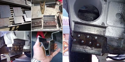
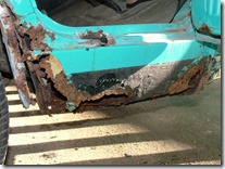
I’ve chased the corrosion back from the sill all the way to the chassis outriggers now.  The rear one has a hole for the petrol tank filler neck and it’s badly corroded at the bottom behind the jacking point.  I deliberated for a while about just repairing the bottom but the thought of trying to remake the afore mentioned hole whilst grovelling underneath left me cold.  I decided to make a whole new outrigger on the bench and graft it on where the cancer ends.  Let the fabrication begin.

I sketched up the piece to be made and took as many measurements as I could from the remains of the original.  It can be really tricky to find suitable reference points to get all the dimensions right and it took a considerable amount of time before I was satisfied. Then I marked out some 18 gauge and started cutting and folding.  I used a plywood template as a guide for the air nibbler to cut the holes which I then flared to accept the tube I created for the filler neck hole.  I’ll cut the old one off and slot the new one into the void created, then MIG weld all around it.  Doesn’t that sound easy.

That’s always our favourite excuse isn’t it?  “Yes dear, I’m going to fix the leaking tap.  I’m sitting here reading Motorsport Magazine because it’s all in the preparation. You can’t rush these things!”

Well sometimes it’s true.  I’ve spent the last few days sitting, looking and thinking about how to proceed with my repairs.  To get as close to the original construction methods with my repair panels as I can.  It’s critically important too, with a vehicle that you simply can’t by parts for cocking it up would be catastrophic.

I’ve tried to reverse engineer the foot well, wheel arch and sill non-destructively.  Work out where the original panel start and finish.  Where they overlap and join and therefore how I can unpick the stiches, saving the good parts and replacing the bad.  I’ve ascertained there will be some casualties along the way and investigated how to replace them before I destroy the originals.

One such piece is the A-Pillar.  It’s shot, with a stress fracture right across it at the door hinge.  It also traps a repair panel I made earlier but have yet to fit.  I will never find a replacement and it is absolutely critical to the strength of the vehicle.  So I had a bash (pun intended) at making one using a hammerform.  It’s come out quite well.  I have a bit of dressing to do to pretty it up a bit but the structure is there.  The stress all got a bit too much for it at the bottom but I’m happy to graft a bit on there to finish it off.

View albumView albumView albumView albumView albumView albumView albumView albumView albumView albumView albumView albumView albumView album

DSCF1980It’s funny how one thing leads to another.  The front wheel arches on Pandora are shot, so obviously I’ve been drawing up plans to make a new petrol tank!

How does that work?

Well the arch meets the sill behind the wheel.  The sill is shot, in best Blue Peter fashion, here’s one I made earlier.  I know the inner sill behind it is also shot and I need to cut away the rust and repair it too.  Right behind the inner sill is the petrol tank.  I didn’t want to go nuts with the plasma cutter when the tank is right behind it, so I dropped it down.  I soon realised that the tank was also shot, hence the mission to create a new one.  I’ll let you know how that goes.

View albumView albumView albumView albumView albumView albumView albumView album

In the meantime I’ve been waving the plasma cutter round like Darth Vader’s light sabre. Sometimes even making that “Whhaaarrm Whhaaarrm” noise and breathing heavily.  Plasma cutters are fun!  Now I can see what I’m up against…

It’s still pretty crazy here at the Scuderia Obsoleto.  I’ve passed Microsoft System Centre Configuration Manager 2012 certification this week and now have a couple of weeks to learn everything I need to know to pass Cisco CCNA certification.  So I’ve not got a lot done on any of the fleet!

Last time I posted I was trying to free hand a front valance corner because my FSP was not particularly great.  The original panel was all lumps and bumps and pretty ugly looking.  I got my replacement piece to somewhere near the right shape and decided I needed to really see the original before going any further.

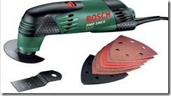
bosch_pmf-180EShifting old paint, underseal and filler is a particular bugbear of mine right now.  I don’t have the space to media blast large parts and I seem to spend longer stripping the crap off my old panels than I do making the new ones.  So I recently bought one of these:

It’s not a quiet thing by any means but with the scraper blade on it’s pretty effective at removing underseal and sound deadening.  Which is where the element of surprise comes in.

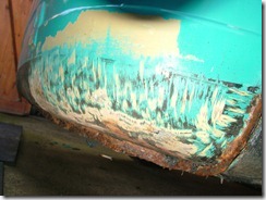
DSCF1975Once the snow melted I went and grovelled on the floor with my new jiggity thingy and started scraping.  It turns out the valance is actually in better shape than I thought.  It has a few dents from insensitive parking but it isn’t stuffed with filler at all.  All the gnarly lumps and bumps were underseal, presumably applied with a trowel.  So I’ve put the brakes on with the new valance until I can get underneath and evaluate the situation a little more thoroughly.  I might just get away with making a new flange….

Crazy days have ensued at the Scuderia Obsoleto.  I’ve been snowed under and not just by the weather.  That pesky day job has been getting in the way again.  Work has been manic and I’ve been studying hard to update some of my IT certification.  I still have some more to do.

I’ve been juggling home maintenance, helping out a few friends and watching my oldest nephew get institutionalised.  He’s away on his honeymoon now, as it was the “institution” of marriage.  So I’ve picked up some hammers and I’m getting back after it.

On the agenda while I’ve only been “bit & bobbing” was the front valance.  This is mainly filler and patchwork plates, so my FSP wasn’t particularly accurate.  I’ve not been taking it for gospel, instead using a more freehand approach to get one end looking right.  Then I’ll make a better FSP from it to use for the other corner.  They have to match each other, not the crap that I cut off.  The section between the two corners should be a doddle by comparison.  I’ll let you know how that works out for me Winking smile

Sometimes you just have a change of plan and that’s what I did with the engine cover.  Instead of re-skinning the spare cover I picked up I decided to leave that one in tact.  There is little to no corrosion on it but the skin has some dings and dents.  I decided it would be an interesting exercise to see if I can straighten this out, I might be able to learn some valuable lessons from it.  Not now but in the future.  So I set about the original engine cover and removed the skin.  It was stuffed with a lot of stringy filler and badly corroded all around the outside.

I need to find a better way to strip paint off panels, I really do!  Getting the frame structure for the engine cover back to bare metal took longer than the repairs did but finally I got there.  After Nitromors, Caustic Soda, hot air gun, rotary nylon and wire brushes, flap wheels, scrapers and sand blasting!

With the paint gone the extent of the corrosion could be assessed and it was pretty bad.  I had to make new sections top and bottom and graft it all together.  My new improved metal folder proved to be improved but not perfect so a bit of manipulation was required.  Ultimately it all came together and I was able to put the new skin on the repaired frame for a test fitting.  Not bad at all.

I decided to bond the two pieces together using structural panel adhesive.  For two reasons really, my spot welder tips are too big to fit the lip on the panel and I wanted to make sure the internal surfaces were better protected than they were when they left the factory.  Everything got a liberal coating of zinc primer before bonding and the end result is quite satisfying.  I can’t wait for the warmer spring when I can apply some paint and see how it looks.

View albumView albumView albumView albumView albumView album

The exhaust went on my friend’s 500 Sporting this week, so I spent some time yesterday fitting a replacement with him.  A pretty straight forward task which didn’t take long.  While the weather was good we took a look at his Barchetta, which has been flattening the battery when left standing.  I suspected the diodes in the alternator were allowing reverse flow, as the charge rate isn’t brilliant either but after disconnecting the alternator there was still a drain.  The previous owner has wired the stereo to be permanently live and disconnecting this reduces the current drain significantly but the jury is still out on whether this is the cause.

I’ve been patiently working at removing the paint from the frame of Pandora’s engine cover. For large areas of panel I favour the polycarbide preparation disks that fit on an angle grinder.  They strip paint in seconds with no damage to the metalwork.  Unfortunately they get ripped to pieces by edges, corners, bolt holes and the like, so no good for the job in hand.  So I thought I’d turn to a faithful old helper… Nitromors.

This stuff used to be the de-facto paint stripper by which all others were measured and would fetch paint off a body panel in minutes.  It’s active ingredients being volatile organic compounds, it has recently fallen foul of the EU’s ban on anything that actually works.  Replacing the VOC’s with New Improved Enviro-Bollocks has resulted in a product that does sweet F.A.!  It’s like losing an old friend.

Progress on the engine cover has been steady over the last week or so.  After modifying my Sealey metal folder I was hopeful of a pretty good result with bending the flanges on my nicely wheeled panel and it did a fair job.  Far more precise and uniform than was possible before my modifications but in all honesty still not as crisp as the edges on the original.  I tried a number of things to crisp them up before making a doohickey especially for the purpose.

The simple device I made, by cutting a slot in a square drift allows me to hammer down on the edge of the flange to drive into the corner whilst at the same time preventing the flange from distorting.  The slot is a couple of millimetres shorter than the flange, thus ensuring I don’t damage the face.  Used alternately with a slapper & dolly on the side of the flange I smartened up the angle pretty well.  It might need a bit more work when I try fitting it but we’ll see…  A little shrinking of the edges produced the right profile to the panel and it started to look pretty good.  Of course this brought me to just the point in the production process where you can really balls it up.

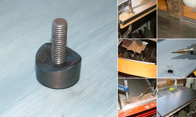
The handle passes through the skin with a shouldered hole. The aperture is 29mm but the shoulder is a couple of mill deep so the hole size needed to be 25mm.  I own one hole punch…it’s 30mm.  After a brief period of swearing and stamping my foot I realised that the punch had a nice taper on the back edge that might prove useful after all.  A test piece confirmed that it was spot-on for starting the shoulder!  After carefully transposing the position from my paper template I drilled and used the punch to create a witness mark.  A step drill and die grinder soon roughed out the hole and after hand finishing with a file I ran the punch again with an improvised flaring attachment.

After a whizz round with the aviation shears… A pretty passable engine cover skin.  Now if only I had something to attach it to.